Choosing an RF connector by appearance alone can lead to mismating, impedance problems, or a mechanically unsuitable design. Interfaces that look similar may use different coupling methods, occupy different panel space, and support different frequency ranges.
An RF coaxial connector is a controlled-impedance electrical interface designed to join coaxial transmission paths while maintaining shielding and limiting impedance discontinuity at radio and microwave frequencies.
This guide compares six widely used RF coaxial connector types: SMA, SMB, BNC, N-Type, MCX, and SMP. Published frequency limits vary by part, cable, and termination, so family-level figures should be used only to create a shortlist.
A practical starting point:
Choose SMA when compact size and threaded retention are important.
Choose SMB or MCX when quick snap-on mating is preferred.
Choose BNC for frequent manual connection in test or video equipment.
Choose N-Type for a rugged threaded interface, or SMP for compact blind-mate designs.
RF Coaxial Connector Types Comparison
The ranges below are representative values based on published specifications for standard connector families. Common designs may support SMA up to 18 GHz, SMB up to 4 GHz, MCX up to 6 GHz, 50Ω N-Type up to 18 GHz, and 50Ω BNC up to 4 GHz, while some SMP connector series are designed for applications up to 40 GHz. Actual performance depends on the connector structure, mounting method, cable, and termination, so the selected product data sheet should always be checked before final approval.
| Connector type | Coupling | Common impedance | Representative capability | Typical selection reason |
| SMA | Threaded | 50Ω | DC to 18 GHz for standard designs | Compact, secure connection for microwave and test systems |
| SMB | Snap-on | 50Ω or 75Ω | DC to 4 GHz for common designs | Fast mating in compact equipment |
| BNC | Bayonet | 50Ω or 75Ω | About 4 GHz for standard RF designs | Tool-free access for test, video, and control equipment |
| N-Type | Threaded | 50Ω or 75Ω | Up to 18 GHz in published 50Ω families | Rugged antenna and outdoor-equipment connections |
| MCX | Snap-on | 50Ω or 75Ω | DC to 6 GHz for standard families | Small PCB, GPS, and embedded wireless connections |
| SMP | Push-on or snap-on | 50Ω | Up to 40 GHz in published families | High-density board-to-board and blind-mate links |
A right-angle body, cable termination, or PCB launch can reduce the usable range compared with another part in the same family. The table is therefore a comparison aid, not a qualification document.
How SMA, SMB, BNC, N-Type, MCX, and SMP Differ
SMA uses a threaded interface and combines compact dimensions with firm mechanical retention. Our SMA RF coaxial connectors are suitable for applications such as antennas, RF modules, microwave equipment, and laboratory instruments. They take longer to mate than snap-on interfaces but are less likely to disconnect accidentally.
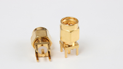
SMB is a snap-on subminiature interface intended for quick connection. Our SMB coaxial connector range includes different cable and mounting structures. SMB should not be confused with SMP; although their names are similar, their interface dimensions and mating structures are different.
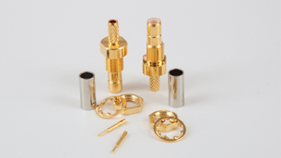
BNC uses a bayonet lock that connects with a short twist. This makes it practical on oscilloscopes, test instruments, video equipment, and control panels. An RF BNC connector may be designed for either 50Ω or 75Ω, so impedance should be checked rather than inferred from appearance.
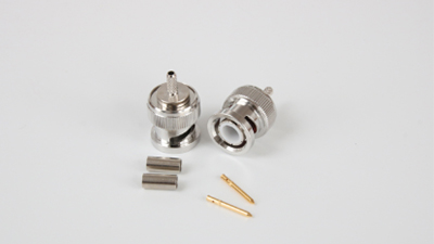
N-Type is larger than the subminiature families and uses threaded coupling. It is commonly considered for antenna feeds and equipment requiring a robust cable interface. As an N type RF connector manufacturer, we provide product drawings for checking connector gender, cable compatibility, and mounting dimensions before sampling.
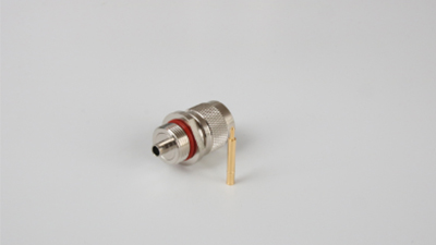
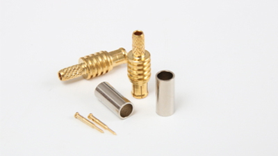
MCX combines a small body with snap-on mating. It suits compact layouts where a connection may need to be serviced without removing a threaded coupling nut. Our RF coaxial electronic MCX connector options include cable-mount and board-mount configurations for space-constrained RF layouts.
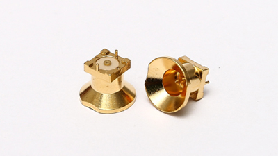
SMP is designed for small, high-frequency interconnects and can support blind mating when used with the correct bullet and receptacle arrangement. Our SMP RF connector series is relevant to dense modules and board-to-board RF links where alignment and available space must be considered together.
How to Select the Right RF Connector Type
When comparing RF coax connector types, begin with the complete system rather than a familiar connector name.
Match impedance across the connector, cable, and equipment port.
Check the operating band against the exact connector and termination.
Choose threaded, bayonet, or snap-on coupling according to retention and access needs.
Confirm cable-mount, bulkhead, panel-mount, or PCB-mount construction.
Review vibration, moisture, temperature, and expected mating frequency.
When comparing microwave connector types, frequency is only one filter. A connector may meet the electrical target but still be unsuitable because of cable bend radius, panel thickness, connector orientation, or limited mating access.
For example, a threaded SMA connector may be electrically suitable but difficult to tighten inside a crowded enclosure. An MCX connector may save space but provide less resistance to accidental disconnection. An N-Type connector may offer a mechanically robust interface but require more panel area than the equipment can provide.
Common RF Connector Selection Mistakes
The most common error is assuming every part in one connector family has identical performance. Connector geometry may be standardized, but electrical results depend on the individual design, material, cable, and termination.
Another error is identifying connector gender only by the external body. Gender is normally determined by the center contact. Reverse-polarity connectors require even greater care because their center contacts differ from conventional interfaces while the outer coupling structure may appear familiar.
Before requesting samples or a quotation:
Specify connector series, gender, and polarity at both mating sides.
State the required impedance and actual operating-frequency band.
Identify the cable type or provide PCB and panel drawings.
Confirm straight, right-angle, bulkhead, or flange construction.
Request model-specific dimensional and electrical data.
These details reduce the risk of mismating, impedance discontinuity, and mechanical interference during assembly. They also give the connector supplier enough information to recommend a configuration that can be tested under the customer’s actual operating conditions.
Summary
SMA, SMB, BNC, N-Type, MCX, and SMP solve different mechanical and electrical problems. Start with impedance and frequency, then compare coupling, available space, mounting, environment, and service access. Use family-level data to create a shortlist, but approve the final connector only after reviewing its drawing, cable compatibility, and model-specific specifications.
RF Coaxial Connector Types FAQs
Which RF connector type is best for high-frequency applications?
There is no universal best type. SMA is widely used for compact microwave connections, while SMP is often selected for high-density or blind-mate designs. The correct choice depends on the exact frequency, launch, cable, and mechanical arrangement.
What is the difference between SMA and SMB connectors?
SMA uses threaded coupling, while SMB commonly uses snap-on coupling. SMA prioritizes mechanical retention and broader microwave use, while SMB prioritizes fast mating in compact equipment.
Is BNC a 50Ω or 75Ω connector?
BNC is available in both 50Ω and 75Ω versions. The selected version must match the cable, equipment port, and signal-path impedance.
Why is N-Type larger than SMA or MCX?
N-Type uses a larger threaded interface intended to provide a robust cable and equipment connection. It therefore requires more panel and routing space than subminiature interfaces.
Is MCX the same as SMB?
No. Both use compact snap-on coupling, but their interface dimensions differ and they are not directly interchangeable.
When should an SMP connector be used?
SMP is suitable for compact, high-density RF modules, including board-to-board and blind-mate arrangements. Alignment, detent style, and the associated bullet or receptacle should be reviewed during mechanical design.
Allen Chen
Hi, I’m the founder & managing director of Baierde Electronic, Allen Chen, an expert in RF coaxial connectors, and I Initiated the current business venture in 2009.
Over 20 years of expertise in RF coaxial connectors, with hands-on proficiency spanning design, development, and high-volume manufacturing.
Leading high-performance teams to deliver 16 years of unbroken revenue growth, achieving $6+ million sales via strategic product positioning, optimized supply chains, disciplined cost management, and uncompromising quality standards.


