N-Type connectors are commonly used in antennas, wireless infrastructure, test equipment, and outdoor RF installations because their threaded coupling provides a secure mechanical connection. However, purchasing mistakes can still occur when connector gender, impedance, or adapter direction is identified from the outer threads alone.
An N-Type connector is a screw-coupled RF coaxial connector with a standardized center contact and outer-conductor interface for transferring radio-frequency signals between cables, equipment, and antennas.
The interface is defined by IEC 61169-16, which covers Type N connectors with a 7 mm inner diameter of the outer conductor and characteristic impedance options of 50Ω and 75Ω.
Performance is not identical across every N-Type product. As an experienced N type RF connector manufacturer, we provide 50Ω N-Type connectors with a published frequency range of 0 to 11 GHz. Some precision Type N products available in the wider market may be rated to higher frequencies, so engineers should always review the data sheet for the selected model rather than assuming that every N-Type connector has the same upper frequency limit.
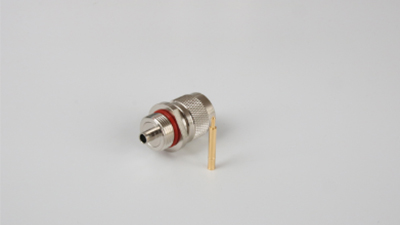
Male N Connector vs Female N Connector
A male N connector normally has a center pin, while a female N connector has a center socket. Connector gender is determined by the inner conductor rather than the visible outer thread. This distinction is important because a panel-mounted female connector can have external threads and may be misidentified when someone looks only at the connector body.
Use this identification sequence:
Look at the center contact first: a pin indicates male and a socket indicates female.
Check whether the component is a cable plug, panel jack, bulkhead connector, or equipment port.
Confirm the product drawing when ordering right-angle, reverse-polarity or customized parts.
In conventional N-Type terminology, a plug usually corresponds to a male interface and a jack to a female interface. We offer different cable-mount and panel-mount structures, so the technical drawing should be checked instead of relying only on a product photograph.
| Selection point | Male N connector | Female N connector |
| Center contact | Pin | Socket |
| Common name | Plug | Jack |
| Typical position | Cable termination or equipment lead | Panel, bulkhead, antenna or equipment port |
| Mating requirement | Connects to a female interface | Connects to a male interface |
| Main item to verify | Cable compatibility and termination | Mounting dimensions and panel structure |
Gender describes the mating interface, not the body shape. A straight cable plug, right-angle plug, and panel-mounted plug can all be male if their center contact is a pin.
50Ω vs 75Ω N-Type Connectors
Impedance is an electrical requirement rather than a cosmetic option. A 50Ω RF path should use a 50Ω connector, cable, adapter, and equipment port. The same principle applies to a 75Ω transmission path.
TE Connectivity identifies 50Ω N-Type connectors as common in wireless data, cellular, and instrumentation systems, while 75Ω versions are generally associated with cable television infrastructure.
Attempting to force a mismatched pair can damage the contacts. Even where parts appear to touch, the impedance discontinuity can increase signal reflection and reduce system performance.
| Requirement | 50Ω N-Type | 75Ω N-Type |
| Common system context | Wireless communication, antennas, cellular and instrumentation | Cable television and 75Ω distribution systems |
| Center-contact geometry | Designed for a 50Ω interface | Uses a smaller center conductor |
| Direct substitution | Not recommended | Not recommended |
| What must match | Port, cable, and adapter impedance | Port, cable, and adapter impedance |
Before approving a connector or adapter, confirm:
The impedance shown on the drawing or model-specific data sheet.
The required operating frequency rather than the connector family’s theoretical limit.
The cable type, termination method, and panel-mount dimensions.
Environmental requirements such as moisture protection and vibration resistance.
The mating interface and gender at both ends of the RF connection.
An adapter can correct connector gender or family, but it cannot safely correct an impedance mismatch. A 50Ω-to-75Ω transition requires a properly designed matching device when electrical matching is necessary.
How to Choose N-Type Adapters
Our N-Type Adapters are designed for RF connections where two existing interfaces cannot be connected directly because of gender, orientation, or connector-family differences. The adapter description should identify both interfaces clearly.
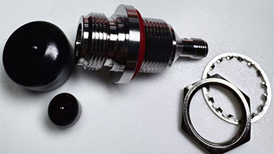
For example, an N male to N male adapter joins two female ports, while an N female to N female adapter joins two male connectors. An N male to N female adapter may extend a connection, change its mounting arrangement, or provide a right-angle transition.
Search phrases can describe the same physical arrangement in different orders. “N female to N male adapter” and “N male to N female adapter” may both describe a male-to-female through adapter. However, the order can matter when the adapter has a bulkhead mount, flange, or right-angle body, so buyers should still check the drawing.
| Adapter search term | Physical configuration | Typical purpose |
| N male to N male adapter | Male interface at both ends | Join two female ports |
| N female to N female adapter | Female interface at both ends | Join two male cable ends or ports |
| N male to N female adapter | One male and one female end | Extend a connection or change mounting arrangement |
| N male to N female right angle adapter | Male and female ends with a 90-degree body | Reduce cable bending near a panel |
| TNC to N Type adapter | One TNC end and one N-Type end | Connect equipment using different RF connector families |
A TNC to N Type adapter requires more than choosing two connector names. Both gender and impedance must be stated. See our TNC Adapters when a project requires a transition between these two threaded connector families. For projects involving several possible interfaces, visit our RF coaxial connectors category to compare connector size, coupling style, and application before selecting an adapter.
Frequency, VSWR and Mechanical Fit
“N-Type” identifies an interface family; it does not provide a universal performance rating. For the N-Type connector series shown on our product page, we publish a frequency range of 0–11 GHz, a maximum VSWR of 1.30, and durability of 500 mating cycles. These values are useful for initial screening but should be confirmed against the current specification for the selected model before approval.
A higher frequency rating does not automatically make one adapter more suitable than another. The complete connection must still have the correct impedance, gender, mounting structure, and cable transition. Each additional adapter also creates another RF interface, so it should solve a genuine compatibility or installation problem.
Use this procurement checklist:
Record the connector required on side A and side B, including gender.
Match 50Ω or 75Ω across the complete signal path.
Specify straight, bulkhead, flange, or right-angle construction.
State the actual operating-frequency range of the system.
Provide the mating-port drawing when interface dimensions are uncertain.
Request model-specific electrical and environmental data before qualification.
Summary
Choose an N-Type connector by checking the center contact first, followed by impedance, frequency, mounting, and cable compatibility. Do not mate 50Ω and 75Ω versions. When selecting an adapter, specify both connector ends and the required body orientation. Reviewing drawings and model-specific data before sampling is the most reliable way to avoid gender, impedance, and mechanical-fit errors.
N-Type Connector FAQs
What is an N Type RF connector?
An N Type RF connector is a threaded coaxial interface used to connect RF cables, antennas, and equipment. Although the mating interface is standardized, frequency range, sealing, materials, and electrical ratings vary between product models.
How do I identify a male N connector?
Check the center contact. A male N connector normally has a center pin and is commonly described as an N plug. The outer thread alone should not be used to determine gender.
How do I identify a female N connector?
A female N connector normally has a center socket and is commonly called an N jack. Female interfaces are frequently found on equipment panels, antennas, and bulkhead-mounted connections.
Can 50Ω and 75Ω N-Type connectors be connected?
They should not be treated as compatible. Their center-contact dimensions differ, and mating them can cause mechanical damage as well as an impedance mismatch.
What does an N female to N female adapter do?
It provides female N interfaces at both ends. It is commonly used to join two male N connectors, cable plugs, or equipment interfaces.
When should I use a TNC to N Type adapter?
Use one when an existing TNC interface must connect to an N-Type cable, antenna, or device. Confirm the required gender, impedance, frequency, and body orientation at both ends before ordering.
Allen Chen
Hi, I’m the founder & managing director of Baierde Electronic, Allen Chen, an expert in RF coaxial connectors, and I Initiated the current business venture in 2009.
Over 20 years of expertise in RF coaxial connectors, with hands-on proficiency spanning design, development, and high-volume manufacturing.
Leading high-performance teams to deliver 16 years of unbroken revenue growth, achieving $6+ million sales via strategic product positioning, optimized supply chains, disciplined cost management, and uncompromising quality standards.


